CCT Doesn’t Predict Circadian Impact

Two of my IES Color Committee friends and colleagues, Tony Esposito and Kevin Houser, have just published a paper in Scientific Reports that looks at the common assumption that CCT can be used to assess circadian entrainment and other biological impacts of light. The assumption by many is that high CCT light contains the blue wavelengths necessary for circadian entrainment, and that assumption is emphasized in the marketing a wide range of tunable white fixtures.

Their study used a five-channel LED system in a full scale model of a room. The LEDs were used to create over 200,000 SPDs across a range of color temperatures and illuminance levels. They found that CCT alone is not an accurate predictor of the spectral content of the light. Since the three major systems used to predict “biological potency” of light – CIE melanopic Equivalent Daylight Illuminance (mel-EDI), Equivalent Melanopic Lux (EML), and Circadian Stimulus (CS) – all use spectral analysis to understand biological impact, using CCT alone is simply inadequate. High CCT may correspond to circadian response, or it may not. They conclude their paper by saying

The lighting industry is experiencing rapid transformation as we expand our awareness of the non-visual impacts of light on humans. It is pertinent that we develop measures, methods, and strategies for implementing architectural lighting solutions that support these non-visual impacts. To do so, we need accurate and predictive measures of the biological potency of light that are based on sound science. In this study, we have argued that CCT is conceptually inappropriate for this purpose and performed a numerical analysis demonstrating that significant variation in circadian stimulus and melanopic equivalent daylight illuminance exists at any fixed CCT and photopic illuminance, making CCT an inappropriate proxy of those measures. Using CCT as a proxy for the biological potency of light cannot be justified.

Understanding that CCT doesn’t correspond with biological impact, it becomes important that designers understand the three systems and push manufacturers to begin providing the relevant information.

Predicting LED Lifetimes

Recently, a corporate client asked me to specify only LED fixtures with a lifetime of 100,000 hours, and preferred fixtures with a life of 200,000 hours.  I don’t know where they came up with these numbers, but my reply was that an L70 of 100,000 hours or more cannot be validated through standard testing procedures.  Here’s why.

To begin with, LEDs themselves don’t experience catastrophic failure the way incandescent and fluorescent lamps do. The don’t stop making light, but their output declines over time.  Today the generally accepted calculation of the life of an LED is called L70, which is the length of time before the light output has fallen to 70% of initial output.

The IES approved lifetime calculation method begins by collecting data using the procedure described in LM-80 (ANSI/IES LM-80 Measuring Maintenance of Light Output Characteristics of Solid-State Light Sources). Please note that LM-80 measures “LED packages, arrays, and modules” not fully fabricated fixtures, and there’s some dispute about whether or not testing bare modules is appropriate.  However, it does permit module manufacturers to test once and derive a lifetime, rather than every fixture manufacturer testing every fixture with every module they want to offer, which would be incredibly burdensome and expensive.

LM-80 requires a minimum collection time of 6,000 hours (250 days) but sets no upper limit.  If manufacturers want to use the data they’ve collected and project future performance they use the calculation procedure in TM-21 (ANSI/IES TM-21 Projecting Long-Term Luminous, Photon, and Radiant Flux Maintenance of LED Light Sources).  Importantly, TM-21 only permits data to be projected to six times the LM-80 data collection time period.  This is because of uncertainties involved with longer predictions (see PS-10-08 IES Position on LED Product Lifetime Prediction at https://www.ies.org/advocacy/position-statements/ps-10-18-ies-position-on-led-product-lifetime-prediction/).  So, an L70 of 50,000 hours is based on at least 8,333 hours of LM-80 testing.  That’s 347 days.

Thus, to say that an LED has an L70 100,000 hour life would require a data collection period of 16,667 hours (695 days), or 1,390 days (3.8 years of continuous testing) for a life of 200,000 hours.  Today, no LED manufacturer conducts LM-80 tests for that extended period of time because the lifetime of a given LED product is too short.  By the time you’ve finished a 4 year long test, the LED being tested is out of production and replaced by something new.  In the future, when the LED industry has matured and we’re no longer seeing continuous improvements in efficacy, color rendering, etc., they may test for that long, but not now.

Where do these 100,000 hour and longer lifetimes come from?  It seems that some manufacturers are using an internally generated prediction to get to these numbers.  The thing is, we don’t know what’s involved in that prediction, which means we can’t validate it or compare it to any other prediction.  We just have to take their word for it. With the LM-80/TM-21 procedure, on the other hand, we know that testing labs, regardless of who or where, are using the same procedure and their results should be consistent and repeatable.  That allows us to reliably, confidently compare fixtures by any number of manufacturers.

Updating the CCT Calculation

As I noted in Chapter 9 of the 2nd edition of Designing with Light, we calculate color temperature, correlated color temperature, and distance from the Plankian locus in a perverse way.  The calculations are performed in the CIE 1960 (u, v) chromaticity diagram (which is why distance from the Plankian locus is Duv).  However, since 1960 (u, v) is obsolete, we perform the calculation using CIE 1976 (u’, v’) chromaticity diagram, but then scale the v’ axis by .66 so that we’re using 1976 (u’, ⅔ v’) which is 1960 (u, v).

To complicate things, to present information graphically, most manufacturers transpose these calculations to the 1931 (x, y) chromaticity diagram, resulting in the industry using 2 ½  chromaticity diagrams for various calculations and illustrations.  Unfortunately, they also use 1931 (x, y) to illustrate the gamut of multi-colored luminaires even though it isn’t uniform, making the illustration of questionable value (they should be using CIE 1976 (u’, v’), which is perceptually uniform).

In a counter to this fragmented system, yesterday Leukos published a research article called Improved Method for Evaluating and Specifying the Chromaticity of Light Sources.  Among other proposed improvements to how we perform chromaticity related calculations, it introduces a new uniform chromaticity scale (UCS) diagram with coordinates (s, t), a measure of correlated color temperature (CCTst), and a measure of distance from the Planckian locus (Dst).  Importantly, it makes all chromaticity calculations in a single chromaticity diagram instead of the 2 ½ diagrams we use today.  It’s heavy on the science, but is an important step in fixing our current system.

New Definition of Kelvin Goes Into Effect Today

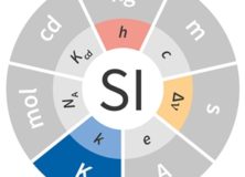
Science geeks everywhere are celebrating World Metrology Day today.   Today has also been chosen by Bureau International des Poids et Mesures (International Bureau of Weights and Measures) to implement changes to the International System of Units or the SI.  The changes are to the definitions of the kilogram, ampere, kelvin, and mole.  

Of special interest to lighting designers, the Kelvin is now defined “by taking the fixed numerical value of the Boltzmann constant k to be 1.380 649 x 10–23 when expressed in the unit J K–1, which is equal to kg m2 s–2 K–1, where the kilogram, metre and second are defined in terms of hc and Cs.”

Yeah, I don’t know what that means, either!  Here’s a link to the full definition and formula.

Specifying Color Quality With TM-30

By now most of us have attended one or more seminars or webinars about IES TM-30 and understand that it is a method of measuring various color rendering properties of a light source and reporting those measurements.  The thing that’s been missing is a recommended set of values that set minimums, maximums and/or tolerances for the various measurements.  This has been true for two reasons.  First, TM-30 is a method and as such was never intended to set recommended values.  The second is that while the science behind TM-30 is solid, the science doesn’t offer any predictions of acceptability.

Good news!  After almost three years of research and tests around the world we’re much closer to establishing a set of recommended values.  At this year’s IES Annual Conference in Boston, Tony Esposito, Kevin Houser, Michael Royer and I will be presenting the seminar “Specifying Color Quality With TM-30”  The description of the seminar is, “This presentation will discuss several research projects which have used the IES TM-30 color rendition framework, and whose results have been used to develop various specification criteria. We will discuss UFC 4-510-01, The Department of Defense Unified Facilities Criteria for Military Medical Facilities, which has already implemented IES TM-30-15 specification criteria.”

During the seminar we’ll review some TM-30 basics, look at several research projects that are helping to establish TM-30 thresholds, and review how to use the TM-30 calculator.  Don’t miss it!


R.I.P. CRI

It’s been a little over two years since the IES released TM-30-15 IES Method for Evaluating Light Source Color Rendition.  In that time TM-30 has seen growing support in the industry and a growing body of evidence for its accuracy and usefulness.  We’ve nearly reached the moment when we can all agree that it’s time to retire CRI and fully adopt a modern, accurate system of measuring and describing the color rendering of light sources.  What’s wrong with CRI?  Quite a bit, so if you’re not up to date on the issue here’s an overview.

In 1948 The CIE first recommended a color rendering index based on a method developed in 1937.  The 1937 method is a fidelity metric (that is, it compares a test light source to a reference light source) that divides the spectrum into eight bands and compares each band to a full spectrum radiator.  In 1965 the CIE finally adopted CIE 13-1965 Recommended method of measuring and specifying color rendering properties of light sources, based on a test color sample method, what today we call CRI Ra or just CRI.  From the start it was apparent that there were problems.  In 1967 a committee was established to correct for adaptive color shift.  Other problems were uncovered, and in 1974 a formal update was published.  Errors were uncovered in the 1974 edition, resulting in a third version in 1994, which is the version we use today.

So far, so good.  Errors are discovered in the method used and are eventually corrected, so what’s the fuss?  The fuss is that the corrections were minor compared to the scope of the errors, and 23 years after the last correction we still don’t have an accurate, up to date system.  In the early 1990s a proposal to update the formula and test color samples failed to gain consensus.  Two subsequent attempts to improve the metric also closed without adoption.  The current problems, as described in the 2011 IES Lighting Handbook, 10th Edition include:

  • Averaging the color shifts of the eight test colors says nothing about the rendering of any single sample.  A large error in one color can be masked by accurate rendering of the other samples.
  • The test color samples are all of moderate saturation so the index doesn’t reveal color shifts in saturated colors.  In addition, the test colors are not evenly distributed through the color space or the spectrum, so light source spectra can be engineered to score higher than visual observation would indicate.
  • The color space used, the 1964 UCS chromaticity diagram, is no longer recommended for any other use.
  • All chroma shifts are penalized, even though research shows that moderately increasing chroma is desirable in many applications.
  • The chromatic adaptation used has been shown to perform poorly and is no longer recommended for any other use.
  • A single number index gives no information about the direction or extent of color shift for any particular color or color range.

Why haven’t these problems been corrected in the past 23 years?  I’m told that there are two issues.  The small issue is that competing scientific interests on the committee advocate new metrics that they’ve developed as a replacement or supplement to CRI.  The larger problem is that manufacturers on the committee don’t want to see any changes that would reduce the CRI of any of their lamps.  From their perspective, it’s better to have a high score on an inaccurate test than a low score on an accurate one.  It seems that internal politics has been preventing updates, corrections, and improvements.

Although many other color rendering metrics have been proposed over the years, none has been adopted by CIE, which has the most significant voice on this issue.  The result is that the sole internationally accepted metric, which has also been written into product specifications and into codes, is CRI.  That began to change in 2015 with the introduction of TM-30. I’ll have more to say about TM-30 in future posts, but for now let’s agree that CRI Ra is broken and CIE is in no hurry to fix it.  A better system exists, and our industry should adopt it.