Nearly all lamps found in residential and commercial spaces are included in the ban, which goes into effect in September. It seems that stage and studio lamps are exempt for now.
Over the past few months I’ve had a manufacturer, a sales rep, and a lighting designer all tell me they think CRI compares a light source to daylight. When I tried to correct one of them the reply was an acknowledgment that an incandescent source is normally used, but daylight can be used, too. Given that the lighting industry has been using CRI since 1965, all three should have known better. On the assumption that they’re not alone in their misunderstanding, let’s talk about reference light sources.
The International Commission on Illumination (CIE for Commission Internationale de l’Eclairage) and the Illuminating Engineering Society (IES) both define color rendering as, “The effect of an illuminant on the color appearance of objects by conscious or subconscious comparison with their color appearance under a reference illuminant.” In other words, we evaluate the color rendering of a given light source by comparing it to another light source. The other light source is called the reference illuminant.
In 1965 the CIE published CIE 13 Method of Measuring and Specifying Colour Rendering Properties of Light Sources. The current version is CIE 13.3-1995. Its General Color Rendering Index, Ra, is usually referred to as CRI. CIE 13.3 says, “the reference illuminant for light sources with correlated colour temperatures below 5000 K shall be a Planckian radiator, and from 5000 K one of a series of spectral power distributions of phases of daylight.”
So, the reference illuminant must have the same color temperature or correlated color temperature (CCT) as the light source being tested. For all light sources with a CCT below 5000 K we use the spectrum of a Plankian, or blackbody, radiator. For all light sources with a CCT of 5000 K or above we use a CIE model of daylight, again at the same CCT as the light source we’re testing.
Regular readers of this blog know that I’m not a fan of CRI, greatly preferring the increased accuracy and depth of information provided by ANSI/IES TM-30 IES Method for Evaluating Light Source Color Rendition. What about TM-30’s reference light source? It’s nearly the same. For CCTs of 4000 K and below it’s a Plankian radiator. For CCTs of 5000 K and above, it’s the CIE model of daylight. TM-30 avoids CRI’s sudden jump between reference illuminants by using a graduated blend of Plankian radiator and daylight over the range of 4001 to 4999 K.
CIE 224 Color Fidelity Index for Accurate Scientific Use is identical to TM-30’s Fidelity Index (Rf) and uses the same reference light sources.
On April 21, 2021, DOE issued a preliminary determination that Standard 90.1-2019 will achieve greater energy efficiency in buildings subject to the code. DOE estimates national savings in commercial buildings of approximately:
4.7 percent site energy savings
4.3 percent source energy savings
4.3 percent energy cost savings
4.2 percent carbon emissions
If the DOE makes a final affirmative determination, and it likely will, states will have two years to certify that they have reviewed the provisions of their commercial building code regarding energy efficiency, and, as necessary, updated their codes to meet or exceed the updated edition of Standard 90.1.
Since 1992, 42 U.S.C. 6833 has required the DOE to evaluate new versions of ASHRAE 90.1 or its successor to determine if adopting the new version as a nationwide minimum standard would improve energy efficiency in commercial buildings. If it does, “eachStateshall, not later than 2 years after the date of the publication of such determination, certify that it has reviewed and updated the provisions of its commercial building code regarding energy efficiency in accordance with the revised standard for which such determination was made. Such certification shall include a demonstration that the provisions of such State’s commercial building code regarding energy efficiency meet or exceed such revised standard.”
Recently, a well-known lighting designer gave a presentation at a well-known lighting conference. During the Q&A he was asked his opinion of TM-30 and replied that it was too hard so he just specified CRI>90. At the risk of sounding like a jerk I have to say that maybe it was too hard for him, but it’s not too hard for most of us. Here is a brief list of new things lighting designers have had to learn over the years.
The introduction and transition to electronic ballasts and transformers meant that we had to learn about reverse phase dimming and control protocols.
The T5 lamp meant we had to change our layout patterns to accommodate lamps that weren’t standard 2’, 4’, and 8’ lengths.
Metal Halide lamps, especially PARs, meant that in exchange for energy savings we had to learn about the color rendering of a new type of lamp, and give up dimming.
Daylight harvesting and daylight responsive designs meant we had to learn about daylight zones, photosensors, and daylight harvesting control systems.
White LEDs meant we had to learn about another light source and its specific pros and cons, including different color rendering properties due to its SPD.
Circadian lighting means we are all in the process of learning how and when to apply the most current scientific evidence to certain project types. Since the science is constantly advancing on this topic, we must be aware and continue to educate ourselves.
Regularly updated energy conservation codes mean that as we begin to memorize the lower LPDs and changes to control and daylighting requirements, we have to relearn that information because it changes every three years.
Most recently, we’re supposed to enthusiastically embrace IoT, adding new hardware and controls to our lighting control systems.
There is a ton of TM-30 educational material available, including posts on this blog here, here, here, here, here, and here. There’s this article on the IES’s FIRES Forum, and this page on the Department of Energy web site. Manufacturers are also providing education including DMF Lighting, Soraa, Premier Lighting, Alphabet, and Lighting Services Inc. Then there are the articles in trade magazines and sites such as Lux Review and Architect Magazine, not to mention many articles in Lighting Design and Application and Leukos (no links because they’re behind the IES login). In addition, there have been presentations at other conferences (some given by me) at the IES Annual Conference, LightFair, and LEDucation.
If that’s not enough for you, let me know. I have a presentation approved for one AIA HSW LU, so if you’re architectural firm wants to learn more let’s set up a presentation. Ditto for lighting design firms and teachers of lighting. If I’m not available there are a half dozen others on the IES Color Committee who regularly give TM-30 presentations. You can learn TM-30. I’m here to help.
The pandemic has certainly distracted me from regular posting here. I’m probably not back to posting weekly, or even monthly, but I do have a new topic and a few things to say about it. The topic is color science as it applies to lighting.
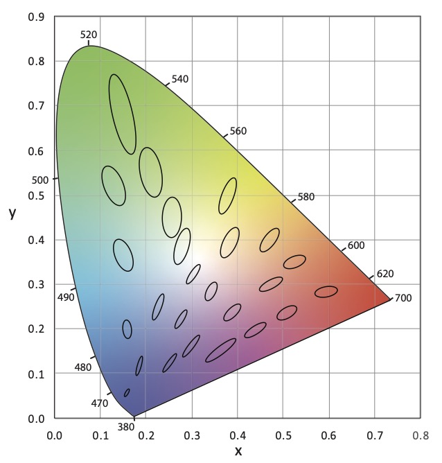
No doubt you’ve seen something like Figure 1 before. It’s the CIE 1931 (x, y) chromaticity diagram and is the most common graphic for showing the range of tunable white luminaires and LED colors and their color mixing possibilities.
Figure 1 CIE 1931 (x, y) Chromaticity Diagram
The thing is, we keep using this diagram even though it has problems and has been replaced twice. The problem is that it isn’t perceptually uniform, which means that the distance between any two color points doesn’t correspond to the perceptual difference between those two colors. This was famously demonstrated in 1942 by David MacAdam. Using 25 chromaticities he had a trained observer, using a device that allowed for the color adjustment of light, attempt to create a side-by side match from different starting points – for example match a yellow sample starting from green, then match it again starting from red, etc. When he plotted the results in CIE 1931 (x, y) the area where color differences could not be detected formed an ellipse as shown in Figure 2. This demonstrated that the color space was not perceptually uniform. If it was the ellipses would have been circles.
These “MacAdam ellipses” have become the default way manufacturers talk about color consistency of their products. You’ll often see statements on cut sheets saying that the LEDs for a particular product line all fall within an X-step MacAdam ellipse (2-step, 3-step, etc.). Want to hear something crazy? In 2014, the International Commission on Illumination (CIE), which sets the standards for most things related to color and light, recommended ending the use of MacAdam ellipses. Why? Look at Figure 2 again. The size of MacAdam ellipses changes as we move around the chromaticity diagram. So does anything related to them, such as Standard Deviation Color Matching (SDCM) another, although less common, measure.
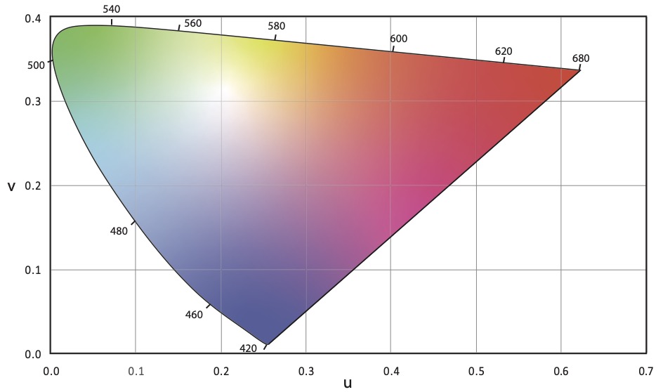
The first attempt to address the uniformity problem resulted in the CIE 1960 (u, v) uniform chromaticity scale (USC) diagram (Figure 3). Correlated color temperature was originally calculated in the CIE 1960 (u, v) UCS.
Figure 3 CIE 1960 (u, v) Chromaticity Diagram
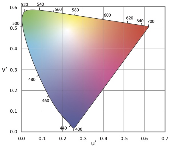
It was later discovered that the CIE 1960 (u, v) USC diagram also was not uniform. To improve uniformity the v-axis was scaled by 1.5, resulting in the CIE 1976 (u’, v’) UCS diagram shown in Figure 4. As the most uniform UCS diagram, CIE 1976 (u’, v’) is the one recommended for use when calculating or evaluating color differences, not CIE 1931 (x, y).
Figure 4 CIE 1976 (u’, v’) Chromaticity Diagram
Correlated color temperature was originally calculated in CIE 1960 (u, v). However, since that diagram is no longer recommended for any purpose by the CIE, we use CIE 1976 (u’, v’) but scale it back to CIE 1960 (u, v). This is described as CIE 1976 (u’, 2/3 v’).
The CIE’s 2014 recommendation mentioned earlier replaced MacAdam ellipses with a circle in the CIE 1976 (u’, v’) UCS. A rough rule of thumb is that one MacAdam ellipse corresponds to a circle with a radius of 0.0011. Unfortunately, it doesn’t seem that any manufacturers have made this transition.
So, our industry is in a situation where we commonly use a 90 year old first generation diagram that was replaced 61 years ago. We calculate CCT in a third generation chromaticity diagram that is 45 years old but tweek the math to refer back to a second generation 61 year old diagram. It’s crazy! No other industry uses a system this convoluted.
Why am I mentioning this? I was recently reminded of a paper that was presented at last August’s IES Annual Conference. Presented by Michael Royer of Pacific Northwest National Laboratory, it proposed using the latest color science to make a fresh start with a single new chromaticity diagram that is very similar to CIE 1976 (u’, v’) where we would calculate CCT, the color temperature bins for LEDs, color differences and the rest. IES members can access the archived presentation after logging in to the IES website.
Full disclosure, I’m on the IES Task Group that is developing this new system. The Task Group is made up of people in academia, design, manufacturing and research from three countries. We’ve refined our work since August and expect to publish these refinements soon. I encourage all of you to look for and learn about this proposal, to attend seminars when available, and to weigh in on this topic. Would our industry benefit from moving to a unified chromaticity system? Is this the right one? How do we educate specifiers and manufacturers? How do we phase in a new system? We can all have a voice in bringing the science we rely on into the 21st Century.
References
CIE. (2014). TN 001:2014 Chromaticity Difference Specification for Light Sources. Vienna: International Commission on Illumination.
CIE. (2018). CIE 015:2018 Colorimetry, 4th Edition. Vienna: International Commission on Illumination.
MacAdam, D. (1942). Visual Sensitivities to Color Differences in Daylight. Journal of the Optical Society of America, 32(5), 247-274.
Royer, M. et. al. (2020). Improved System for Evaluating and Specifying the Chromaticity of Light Sources. In: Illuminating Engineering Society Annual Conference 2020.
The Illuminating Engineering Society’s Recommended Practice 16 Nomenclature and Definitions for Illuminating Engineering (aka RP-16) has long been one of the two reference sources for the definition of lighting related words and phrases – the other being the CIE International Lighting Vocabulary (ILV).
As part of the IES converting all of their publications to an online library format, some publications have been given a new designation. RP-16 is now Lighting Science 1 (LS-1) and is at this link. Bookmark it now!
This semester I decided to look at songs with colors in the title. Of course, Purple Rain is the first one that comes to mind, so here’s the performance from the movie.
But purple isn’t the only color. There’s also raspberry.
Yesterday an addendum to ANSI/ASHRAE/ICC/USGBC/IES Standard 189.1-2017 Standard for the Design of High-Performance Green Buildings was published. The addendum makes changes to Section 8.3.5, which covers lighting. One of the biggest changes is to add TM-30 color rendition criteria to the section on Indoor Lighting Quality. Here’s the relevant text:
8.3.5.3 Color Rendition. At least 95% of lighting power of nominally white lighting within each enclosed space shall be provided by luminaires that meet the following criteria at full light output in accordance with IES-TM-30, Annex E, P2 and F3: 1. Rf of at least 85 2. Rf,h1 of at least 85 3. Rg of at least 92 4. Rcs,h1 of at least -7% but no greater than +19%
Nominally white lighting is lighting that has chromaticity within the basic or extended nominal color correlated temperature (CCT) specifications of ANSI C78.377.
Where a lighting system is capable of changing its spectrum, it shall be capable of meeting the color rendition requirements within each nominal CCT of 2700 K, 3500 K, 4000 K, and 5000 K, as defined in ANSI C78.377, that the system is capable of delivering.
I hope that this is going to put more pressure on manufacturers to improve the color rendering of their luminaires as measured by TM-30, not CRI, and to provide TM-30 information on their cut sheets. If not, they’ll risk not being considered on projects that have TM-30 requirements.
As interest in using light disinfection continues to grow standard setting organizations and manufacturers are becoming more active in this area. The International Commission on Illumination (CIE) has just released a position statement on the use of ultraviolet radiation to manage the risk of COVID-19 transmission.
Here are a few bullet points:
While ultraviolet light ranges from 400 nm to 100 nm, the most effective wavelengths are at around 254 nm and this is generally what is meant by germicidal ultraviolet or GUV.
UV-C has been successfully used for water disinfection and in air handling units for many years. UV-C has also seen a resurgence for use in healthcare environments.
Direct exposure to UV-C can cause photokeratitis (similar to snow blindness) and erythema (skin reddening similar to sunburn) so carefully shielded luminaires are required when used in occupied spaces.
Consumers should be wary of products not approved by consumer safety organizations. Such products could be hazardous to use or may not emit UV-C at all.